SystemC AMS Building Block Library |
||||||||||||||||||||||||||||||||||||||||||||||||||||||||||||||||||||||
|
In the course of the ANDRES project, a Library of configurable SystemC AMS modules was developed at the Vienna University of Technology, and is . The implemented building blocks focus on the field of communication and radio frequency systems, in particular on signal sources, modulation/demodulation blocks, filters, measurement and observation parts. They can be subdivided into three categories of blocks:
The library also contains some example application. One example, an OFDM transceiver, is described here. Download the SystemC AMS Building Block Library here! Examples (Full documentation available with package) Gaussian distributed random NumbersFunctional description
Module definition: noise_gauss(sc_module_name nm, double _variance, double _mean, int _rate); Parameters:
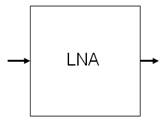
Low-noise amplifier (LNA)Functional description
Module definition: lna(sc_module_name n, double _gain, double _ip3, bool _ideal); Parameters:
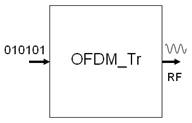
OFDM modulator (OFDM transmitter)Functional description Module definition: template <int N>
Example application: OFDM Transmitter systemThe purpose of this chapter is to show the user how to use the modules from this building block library to model communication systems. We assume that the user who uses this library already has some basic knowledge of SystemC AMS. Based on the previously described modules an OFDM transmitter system is built up (see Figure 11) in this Section.
Figure 11 shows the structure of the transmitter system in our example. First, test data is generated by a test generator and passed to the transmitter. As the test generator the rand_bool module described in Section 2.3 is used and a serial of universal distributed random bits is generated. The transmitter takes these binary signals and modulates them to a high frequency OFDM signal (using Orthogonal Frequency Division Multiplex (OFDM) modulation). The ofdm_semodule described in Section 3.4.19 is used to model the transmitter. The generated signal is then passed via a channel (modelled using the air module described in 3.3.16) which attenuates its input signal and adds noise. After that the signal is taken by a receiver and translated back into a stream of binary bits. In order to model communication systems using the modules in the library the user has to include the respective header data and set the right namespace first:
#include "tuv_ams_library/tuv_ams_library.h" Then the expected modules from the library have to be instantiated in the following way: rand_bool i_ i_stimuli.out(sig_stimuli); stimuli("stimuli",16); where “rand_bool” is the module name, “i_stimuli” is the instance name of the module, “stimuli” and “16” are values for respective parameters of the module. Finally, SystemC AMS signals have to be declared to connect different modules:
sca_tdf::sca_signal Here a signal called “sig_stimuli” is declared and connected to the “out” port of the module “i_stimuli”. Apart from the above mentioned issues the user has to set the time resolution of the simulation using the predefined method “sc_set_time_resolution()”. It is also required to set the sampling rate on at least one port of the modelled system with the method “.set_T()”. For the system described we need the following Section of codes:
int sc_main(int argc, char* argv[])
{
  sc_set_time_resolution(1, SC_PS);	// set the time resolution

  sca_tdf::sca_signal<bool> sig_stimuli;    // declare SystemC AMS signals
  sca_tdf::sca_signal<double> sig_out;
  sca_tdf::sca_signal<double> noise_out;
  ...

  rand_bool i_stimuli("stimuli",16);   // instantiate test generator
  ofdm_se<8> i_tran("transmitter",constl_dim,
                    freq_carrier,freq_bit,data_rate,ampl_se); // instantiate transmitter
  air i_air("air",attent,"gauss_white",n_va,n_mean,data_rate);
						// instantiate channel
  ofdm_re<8> i_receiver("receiver",constl_dim,freq_carrier,freq_bit,data_rate,
1ampl_re);			// instantiate receiver
  drain drn("drn");                    // instantiate drain. This is only a
// module used to consume tokens as we
// can not let a SystemC AMS scheduling
// loop open.

  i_stimuli.out.set_timestep(1/freq_bit,SC_SEC); //Time step has to be set to one of
      the ports in the system

  i_stimuli.out(sig_stimuli);          // connect different modules
  i_tran.in(sig_stimuli);
  i_tran.out(sig_out);
  ...

  // Tracing:
  sca_util::sca_trace_file wave = sca_util::sca_create_vcd_trace_file ("wave");
  sca_util::sca_trace (wave, sig_stimuli ,"stimuli");
  ...

  sc_start(0.05,SC_MS);                // Simulation time: 0.05ms
  return 0;
}
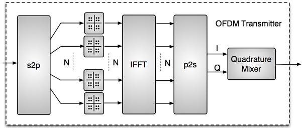
(This is not the complete source code) The transmitter and receiver modules consist again of sub modules, which are contained in the library. Figure 12 and Figure 13 present the internal structure of the transmitter module and receiver module, respectively. The transmitter takes a serial stream of binary digits. By inverse multiplexing, these are first demultiplexed into N parallel streams, and each one mapped to a (possibly complex) symbol stream using QAM modulation. An inverse FFT is computed on each set of symbols, giving a set of complex time-domain samples. These samples are then quadrature-mixed to passband in the standard way.
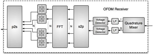
Block diagram of OFDM transmitter The receiver picks up the signal from antenna, which is then quadrature-mixed down to baseband using cosine and sine waves at the carrier frequency. This also creates signals centered on 2fc, so low-pass filters are used to reject these. The baseband signals are then sampled and a forward FFT is used to convert back to the frequency domain. This returns N parallel streams, each of which is converted to a binary stream using an appropriate symbol detector. These streams are then re-combined into a serial stream, which is an estimate of the original binary stream at the transmitter.
The next code Section shows how to use building block modules to build the OFDM transmitter module:
template <int N>
SC_MODULE(ofdm_se){
public:
 //Ports:
 sca_tdf::sca_in<bool> in;            // declare port
 sca_tdf::sca_out<double> out;
 //signals
 sca_tdf::sca_signal<bool> sig_pa[N];  	// declare signals to
 sca_tdf::sca_signal<double> sig_real[N];  // connect sub modules
 ...
private:
  //module instantiation
  s2p<bool,N>* s2p_sub;
  qam_map* qam_mapper_sub[N];
  fft_ifft<N>* ifft_sub;
  p2s<double,N>* p2s_r_sub;
  p2s<double,N>* p2s_i_sub;
  q_mixer_tr* q_mixer_tr_sub;
 public:
  //Constructor
  ofdm_se(sc_module_name n,int qam_p_num,double mixer_fc,double bit_f,int
   dout_rate,double _amp=1)
{
   int mixer_rate=(int)floor(dout_rate*log2(qam_p_num)*mixer_fc/bit_f);
// instantiating modules and connecting them using signals
   s2p_sub = new s2p<bool,N>("s2p_sub",1);  // serial to parallel module
   s2p_sub->in(in);
   for(int i=0;i<N;i++)
     s2p_sub->out[i](sig_pa[i]);

    ...

    ifft_sub = new fft_ifft<N>("ifft_sub","IFFT"); //IFFT module
    for(int i=0;i<N;i++)
      {
	   ifft_sub->in_real[i](sig_real[i]);
	   ifft_sub->in_imag[i](sig_imag[i]);
	   ifft_sub->out_real[i](sig_out_real[i]);
	   ifft_sub->out_imag[i](sig_out_imag[i]);
      }

    ...

    p2s_r_sub = new p2s<double,N>("p2s_r_sub",1); //quadrature mixer module
q_mixer_tr_sub = new q_mixer_tr("q_mixer_tr_sub",mixer_fc,_amp,0.,0.,mixer_rate,false);
    q_mixer_tr_sub->i_in(sig_out_i);
    q_mixer_tr_sub->q_in(sig_out_q);
    q_mixer_tr_sub->out(out); /***/

  }
};
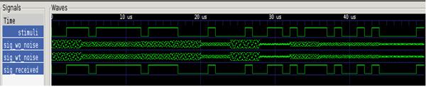
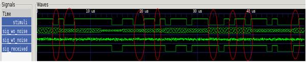
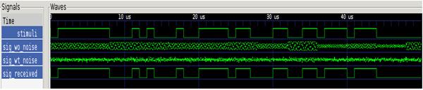
As we can see from the source code the modelling of an OFDM transmitter is quite easy when using the existing modules in the library. Simulation example:
constl_dim = 16,ampl_se=1.0,ampl_re=1.0,n_amp=0.0,atten=1.0
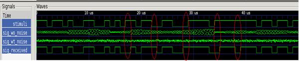
constl_dim = 16,ampl_se=1.0,ampl_re=1.0,n_amp=90.0,atten=1.0
constl_dim = 16,ampl_se=1.0,ampl_re=1.0,n_amp=90.0,atten=0.5
constl_dim = 16,ampl_se=20,ampl_re=0.1,n_amp=90.0,atten=1.0
constl_dim = 4,ampl_se=1.0,ampl_re=1.0,n_amp=0.0,atten=1.0 For questions and suggestions regarding the building block library please contact |
||||||||||||||||||||||||||||||||||||||||||||||||||||||||||||||||||||||